
CUSTOM MANUFACTURING & TOOLING
How Should Buyers Define Silicone Parting-Line Flash and Trim Acceptance?
Define silicone flash and trim acceptance with zoned drawings, measurable limits, boundary samples, inspection methods and production release controls.

DIRECT ANSWER
What B2B Buyers Need to Know
Buyers should define silicone flash and trim acceptance by dividing the part into functional and cosmetic zones, then assigning measurable limits for attached flash, trim witness, mismatch, nicks and loose fragments. Each limit needs a stated inspection method, acceptable-limit-reject samples, defect classification, production trial evidence and change control tied to the current drawing, mold, compound and finishing route.
This guide is written for silicone-product importers, OEM engineers, private-label brands, quality managers, tooling teams, procurement leaders and third-party inspectors. It provides a decision framework rather than legal advice or a universal specification. Product classification, use conditions and destination market should be confirmed before final testing, labelling or compliance decisions.
Key Takeaways
- Zone the part by functional consequence before assigning any flash or trim limit.
- Define attached flash, trim witness, mismatch, nicks, tears and loose fragments separately.
- Pair every numerical or visual limit with a reproducible inspection method and part orientation.
- Approve acceptable, limit and reject samples from the real material, mold and finishing route.
- Use sampling only after defect classes, lot definition and critical-feature controls are agreed.
- Link quotation, tooling maintenance, rework, traceability and change control to the same acceptance baseline.
Silicone Edge Acceptance Decision Matrix
Use separate limits and evidence for each edge condition. Exact values depend on geometry, function, material, mold capability, finishing route and the buyer's approved risk assessment.
| Edge condition | Buyer must define | Evidence for approval |
|---|---|---|
| Attached flash | Zone, measurement direction, maximum extent and loose-particle condition | Section drawing, calibrated measurement or controlled visual method, and boundary samples |
| Trim witness | Permitted remnant, surface transition and protected functional areas | Finished samples from the approved route plus assembly, seal or handling checks |
| Mismatch or step | Datum, profile direction and dimensional limit across the mold split | Tooling review, cavity results and repeatable profile or gauge measurement |
| Nick, tear or gouge | Depth, length, location, defect class and rework prohibition | Limit samples, magnified inspection and product-specific functional verification |
| Loose fragment or residue | Zero-tolerance zones, cleaning method and detection requirement | Controlled cleaning, screening, count reconciliation and lot-release record |
| Cosmetic witness | Viewing condition, color, distance, magnification and acceptable boundary | Approved physical samples supported by controlled photography and inspector agreement |
SECTION 01
Build a Zoned Silicone Flash and Trim Specification
Convert the commercial concept into controlled dimensions, functions and approval criteria before DFM begins.
Start With Functional and Cosmetic Edge Zones for silicone flash trim acceptance
Begin with the finished function, because a single no-flash statement cannot describe every boundary on a silicone part. A thin witness at a hidden nonfunctional split line may be acceptable, while the same condition on a sealing bead, skin-contact edge, optical surface, assembly groove, or food-contact lip can create a functional or cleaning risk. Divide the drawing into named zones before discussing numbers.
For every zone, state which conditions are being controlled: attached flash, trim witness, mismatch or step, tear, nick, gouge, loose fragment, and surface damage. These are not interchangeable defects, so one limit should not be copied across all of them. The factory needs a separate decision for each characteristic that can affect fit, seal, appearance, handling, sanitation, or downstream assembly.
ISO 3302-1 provides dimensional-tolerance classes and flash-classification context for solid molded rubber products, but a standard reference does not select the correct class for a buyer's actual part. The drawing, use conditions, mold concept, inspection method, and approved samples must establish the project-specific requirement. Treat the standard as common language, not as an automatic product approval.
Map Parting Lines, Shutoffs, Vents and Gates
Map the entire parting line, including primary mold splits, insert shutoffs, sliders, vents, overflow points, and gates. A drawing that marks only the most visible circumference can leave high-risk local transitions undefined. We normally review the three-dimensional model and physical sample together so the buyer can see where steel boundaries create unavoidable witness lines.
Classify zones by consequence rather than visibility alone. A hidden edge can be critical if it enters a groove, touches a mating component, traps residue, or controls a seal; a visible edge can be mainly cosmetic when it never contacts the user or assembly. The zone map should show functional, cosmetic, protected, and noncritical boundaries with a clear precedence rule where zones meet.
Define Flash, Trim Witness and Mismatch Separately
Define flash with a measurement direction. Flash length, width, and thickness describe different conditions, and a value without orientation can be interpreted differently by a buyer, toolmaker, operator, and third-party inspector. Show a section view for critical locations, identify the reference surface, and state whether the limit applies before or after the approved finishing process.
Trim witness is the controlled remnant left after flash removal, not necessarily a defect. A flush-cut expectation can encourage over-trimming, which may create nicks or reduce the designed section more severely than a small attached witness would. For flexible lips and sealing features, the team should compare the permitted witness with functional test results rather than pursuing a visually perfect edge at any cost.
Mismatch and offset need their own definition because they originate from mold alignment or shutoff behavior rather than excess film alone. Measuring only the visible fringe can miss a step between the two molded surfaces. If the step influences assembly, sealing, stacking, or appearance, control it as a dimensional or profile characteristic with a suitable datum and method.
SECTION 02
Establish Reproducible Inspection and Boundary Samples
Close the process, material and mold decisions that determine tooling scope, trial evidence and revision cost.
Select a Repeatable Inspection and Measurement Method
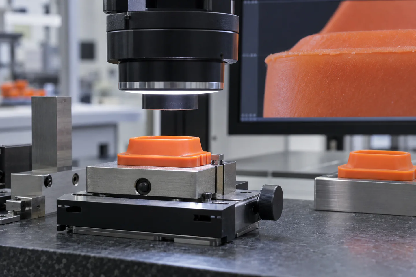
Choose the inspection method at the same time as the limit. A fine edge may be evaluated with a calibrated optical comparator or measuring microscope, while larger accessible features may use a gauge, controlled magnification, or a physical boundary sample. Ordinary calipers are not automatically suitable for soft, narrow flash because jaw pressure and operator angle can distort the result.
Record lighting, background, viewing distance, magnification, part conditioning, fixture, and measurement location. These details are especially important for translucent or dark silicone, where backlighting can reveal a witness that disappears under normal reflected light. The inspection condition should match the risk: cosmetic review can use a defined visual setup, while critical geometry may need instrumented measurement and functional verification.
Run a measurement-system study on the proposed method before using it for shipment decisions. Give several inspectors the same acceptable, borderline, and reject parts in a blinded sequence, then compare repeatability and agreement. If trained inspectors cannot reproduce the classification, the specification or method needs correction before an AQL table is applied.
Approve Acceptable, Limit and Reject Boundary Samples
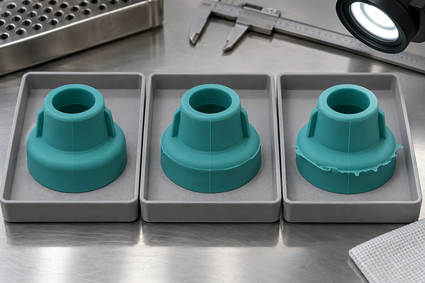
Build three levels of physical reference: acceptable, limit, and reject. Each sample should carry the product code, drawing revision, cavity, molding lot, finishing route, approval date, and protected storage identity. A photograph can support the standard, but it should not replace the physical reference when edge height, texture, flexibility, or loose-particle behavior is difficult to judge from an image.
Use more than one reference when the part has materially different zones. A boundary sample for a broad cosmetic flange may be misleading at a sealing bead or thin membrane. The reference set should represent the actual compound, color, finish, and geometry because contrast, translucency, and hardness change what inspectors perceive.
Escalate Mold and Process Causes Before Over-Trimming
Separate molding control from secondary trimming control. Heavy, irregular, or cavity-specific flash can indicate worn shutoffs, mold damage, vent changes, misalignment, contamination, or an unstable molding window. Increasing manual or cryogenic finishing may temporarily improve appearance while hiding the underlying tool condition and increasing damage risk.
Set escalation triggers for flash trend, cavity pattern, trim time, rework rate, and related defects. When a trigger is exceeded, hold the affected output and review the mold and process before allowing a more aggressive finishing method. A process engineer should decide whether the correct response is maintenance, parameter correction, tooling modification, or a controlled finishing adjustment.
SECTION 03
Control Molding, Finishing and Production Validation
Treat each mold trial as a measured engineering gate rather than a visual sample-selection exercise.
Control Manual, Cryogenic and Rework Instructions
A finishing work instruction should name the approved route and its operating boundaries. For manual trimming, define fixture, tool, blade condition, sequence, prohibited contact areas, maximum interventions, and operator qualification. For cryogenic or mechanical finishing, control equipment, batch load, media, exposure, agitation, screening, cleaning, and the features that require post-cycle inspection.
Define allowable rework separately from first-pass finishing. Repeated trimming or another cryogenic cycle can change dimensions, surface condition, contamination risk, and the probability of tearing a thin feature. State who can authorize rework, how many interventions are allowed, which inspections repeat, and how the reworked quantity remains traceable.
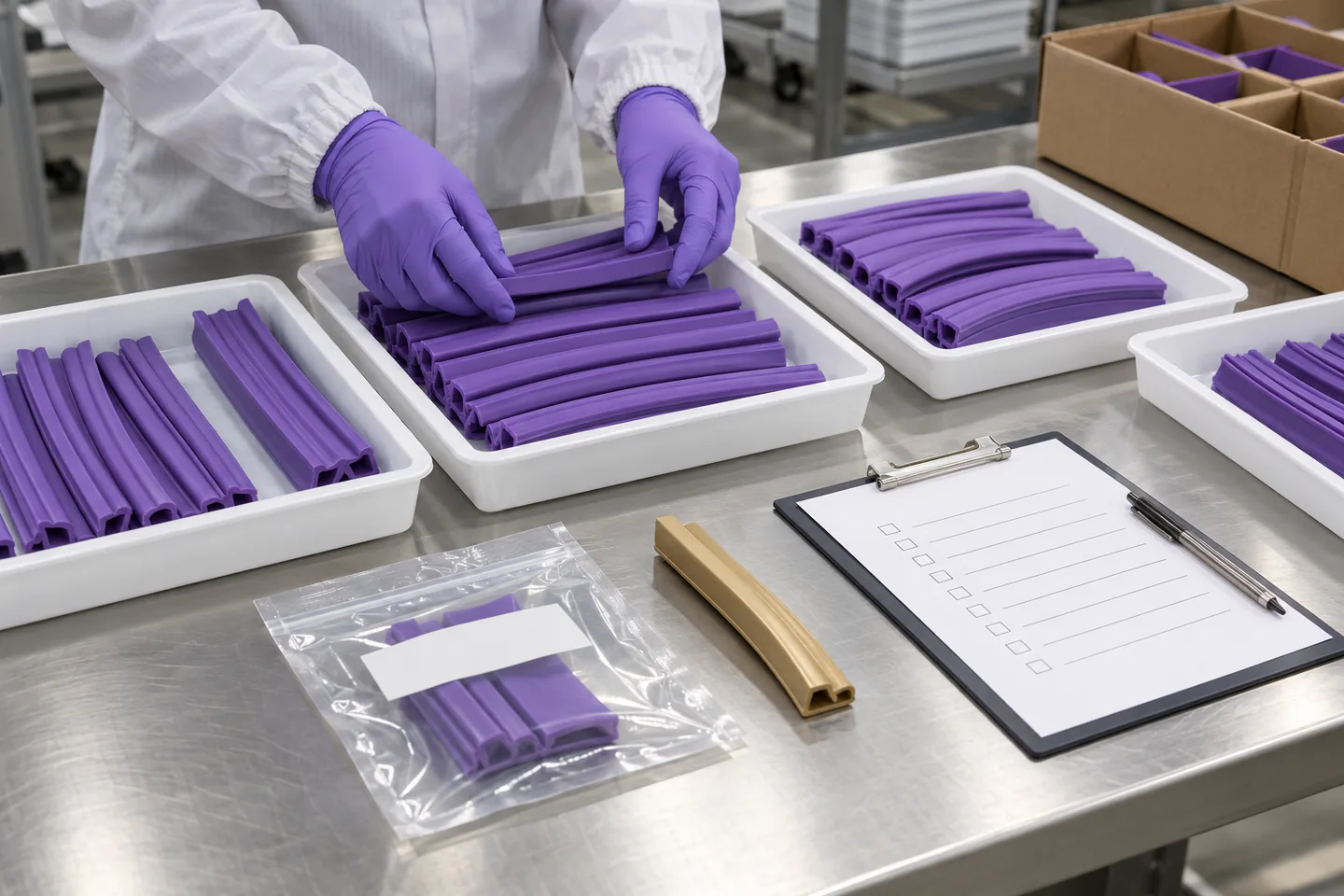
Count and segregate loose fragments. Attached flash, a cut sliver, and media residue present different risks even when the edge itself meets its dimensional limit. The process should include controlled cleaning, visual or automated screening where appropriate, tray discipline, and quantity reconciliation before parts enter final packaging.
Validate the Limit With Production-Representative Trials
Approve the specification with production-representative trials, not a hand-selected presentation sample. Use the intended compound, color, mold revision, cavities, cure or post-cure condition, finishing route, and inspection method. Include typical output and deliberately selected boundary conditions so the team learns whether the proposed acceptance language separates conforming and nonconforming parts reliably.
Review results by cavity and defect location. If one cavity repeatedly produces a wide witness while the others remain stable, a pooled pass rate can hide a correctable tool problem. Cavity-level records also help the buyer distinguish random finishing variation from a systematic mold condition during pilot approval and later complaints.
Connect edge findings to function. Perform the relevant assembly, seal, pull, flex, cleaning, or handling check on parts near the proposed limit, then compare them with nominal samples. ISO 37 offers a controlled method for tensile stress-strain properties of rubber specimens, but bulk-material data alone cannot prove that a particular finished edge is acceptable.
Classify Defects and Build the Lot Sampling Plan
Classify defects by consequence before choosing sampling levels. A loose fragment in a sensitive use, a nick through a sealing lip, or an over-trimmed retention feature may require different control from a minor cosmetic witness on a concealed flange. The buyer and supplier should agree which conditions are critical, major, or minor and document the reasoning.
ISO 2859-1:2026 supplies AQL-indexed sampling schemes for lot-by-lot inspection by attributes, but it does not decide the product's defect classes or make critical features safe through sampling. Use an agreed inspection level, lot definition, switching rule, and acceptance number only after the defect catalogue and method are stable. Critical characteristics may need process controls or complete checks beyond final sampling.
Write the lot definition carefully. Mixing cavities, molding dates, finishing routes, operators, or rework statuses into one inspection lot can dilute a concentrated problem. The release record should allow a failed result to be traced to a controllable production segment without forcing the factory or buyer to guess which units share the exposure.
SECTION 04
Release Lots Through Sampling, Traceability and Change Control
Release production only when drawings, golden samples, inspection records and change authority describe the same revision.
Translate Edge Requirements Into Comparable Quotations
Translate the acceptance standard into quotation assumptions. Tighter limits can require improved steel shutoffs, more tool maintenance, slower manual work, dedicated fixtures, higher magnification, automated inspection, or increased scrap. A supplier cannot compare cost honestly when one RFQ says commercial quality and another silently expects a near-invisible edge everywhere.
Ask suppliers to separate molding capability, finishing cost, inspection burden, expected yield, and tooling-correction options. A low unit price may rely on a broad cosmetic limit, while a higher quote may include protected handling and measurement of critical zones. Compare the same drawing revision, sample plan, forecast, batch size, rework rule, and packaging condition.
Keep capability statements conditional until the production trial is complete. Mold geometry, compound behavior, color contrast, cavity balance, finishing access, and volume all affect the achievable edge. The quotation should state assumptions and identify which trial result will convert them into an approved production baseline.
Preserve Lot Traceability and Defect Trends
Preserve traceability through molding, finishing, inspection, and packing. Temporary containers should identify part number, revision, color, compound lot, molding lot, cavity or cavity group, finishing route, rework status, and inspection status. This prevents accepted parts, unprocessed parts, and parts awaiting disposition from being mixed during busy production periods.
Retain enough evidence to reconstruct a release. Typical records include first-off approval, process parameters, maintenance status, finishing route, in-process checks, boundary-sample identity, final sampling result, defect location, rework quantity, and release authority. The exact retention period depends on contract and risk, but the record should remain tied to the shipped lot.
Use defect trends rather than isolated pass rates. Plot flash location, cavity, trim damage, loose residue, operator or cycle, and rework across repeat orders. A shipment can pass sampling while a worsening trend signals that mold maintenance or process correction should be scheduled before the next lot.
Release Drawings, Samples and Change Control Together
Release the part only when the same acceptance definition appears in the drawing, approved sample set, work instruction, inspection plan, and purchase-order quality agreement. If those documents conflict, operators tend to follow the easiest or newest reference, and inspectors may apply a different rule. A controlled hierarchy and revision owner prevent that drift.
Require written review before changing mold steel, cavity assignment, compound, color, finish, finishing equipment, media, manual tools, fixtures, inspection method, production site, or boundary samples. Not every change requires a full requalification, but the responsible team should document its impact and decide what evidence must be repeated.
For a B2B inquiry, send the three-dimensional file, zoned drawing, use conditions, material and hardness, critical interfaces, expected volumes, present flash examples, finishing preference, inspection method, packaging, and destination. Ask for a DFM review, boundary-sample plan, pilot quantity, capability risks, tooling recommendations, conditional price, and lead time. That information lets the factory respond to a real acceptance problem rather than guess what clean edge means.
ACTION FRAMEWORK
Buyer Checklist Before Commercial Approval
Use this checklist as a meeting agenda. It is intentionally concise so the team can identify missing evidence without replacing its own quality, legal or supplier-management procedure.
| Check | Question | Why It Matters |
|---|---|---|
| Zone map | Are sealing, assembly, contact, cosmetic and concealed edges classified separately? | One universal limit can over-control harmless areas while leaving critical interfaces ambiguous. |
| Defect language | Are flash, witness, mismatch, nick, tear, gouge and loose fragments defined? | Different defects have different causes, measurement methods and functional consequences. |
| Measurement | Does every limit state direction, datum, fixture, lighting and instrument? | Flexible silicone can produce inconsistent results when support and viewing conditions change. |
| Boundary samples | Are acceptable, limit and reject references identified and protected? | Physical standards reduce subjective interpretation but must remain traceable and undamaged. |
| Process route | Are molding controls, finishing method and permitted rework documented? | Aggressive finishing can hide a tooling problem or create damage worse than the original flash. |
| Validation | Were production-representative cavities and near-limit parts functionally checked? | A presentation sample or material report cannot prove finished-edge performance. |
| Sampling | Are defect classes, lot definition, inspection level and critical checks agreed? | AQL sampling is meaningful only after the acceptance language and method are stable. |
| Change control | Which mold, material, route, method and site changes require reapproval? | An accepted edge condition can change when any linked production assumption changes. |
NEXT READING
Continue the Supplier and Product Review
These internal resources connect the guide with Naike Silicone product, factory, customization and inquiry pages. Open the route that matches the next decision in your project.
Compare manual and cryogenic silicone deflashing
Use compare manual and cryogenic silicone deflashing to gather the next level of product, manufacturing or commercial information.
Open internal resource →Review silicone mold parting lines, vents and gates
Use review silicone mold parting lines, vents and gates to gather the next level of product, manufacturing or commercial information.
Open internal resource →Plan mold maintenance for repeat-order consistency
Use plan mold maintenance for repeat-order consistency to gather the next level of product, manufacturing or commercial information.
Open internal resource →Request a custom silicone tooling review
Use request a custom silicone tooling review to gather the next level of product, manufacturing or commercial information.
Open internal resource →Explore all silicone product categories
Use explore all silicone product categories to gather the next level of product, manufacturing or commercial information.
Open internal resource →Review Naike Silicone manufacturing knowledge
Use review naike silicone manufacturing knowledge to gather the next level of product, manufacturing or commercial information.
Open internal resource →PRIMARY REFERENCES
Authoritative External Sources
The sources below are official primary references. Applicability depends on the product, intended use and destination market. Buyers should obtain qualified advice for final legal or regulatory decisions.
ISO 3302-1:2014 Rubber Product Dimensional Tolerances
Official ISO page for dimensional tolerance classes and flash-classification context for solid molded rubber products; it does not select a finishing route or approve a product-specific silicone edge.
ISO 37:2024 Rubber Tensile Stress-Strain Properties
Official ISO page for the method used to determine tensile stress-strain properties of vulcanized and thermoplastic rubbers; finished-lid fit still requires product-specific validation.
ISO 2859-1:2026 AQL Sampling for Lot-by-Lot Inspection
Official ISO page for the current sampling schemes indexed by acceptance quality limit for lot-by-lot inspection by attributes.
BUYER QUESTIONS
Frequently Asked Questions
Can a buyer simply specify no flash on a silicone part?
No-flash wording is usually too vague to manufacture and inspect consistently. A molded part normally has defined steel boundaries, and removing every visible witness can create over-trimming or damage. Divide the part into functional and cosmetic zones, then define attached flash, trim witness, mismatch, nicks, loose fragments, the inspection method, and approved boundary samples for each relevant zone.
What is the difference between flash and a trim witness?
Flash is excess material formed at a mold split, shutoff, vent, overflow, or gate. A trim witness is the controlled remnant or surface evidence left after an approved finishing step. They should have separate limits because a small attached witness may be acceptable while aggressive removal can cut into the functional part.
How should very small silicone flash be measured?
Select a method that can resolve the feature without deforming it, such as a calibrated measuring microscope, optical comparator, gauge, or controlled visual boundary sample. Define orientation, support, lighting, background, magnification, measurement direction, and conditioning. Validate inspector agreement before using the method for supplier qualification or lot release.
Does ISO 3302-1 automatically define the correct flash limit?
No. ISO 3302-1 provides dimensional-tolerance classes and flash-classification context for solid molded rubber products, but the buyer and manufacturer must select and apply requirements appropriate to the actual geometry and use. The drawing, risk zones, method, functional evidence, and approved samples remain project-specific.
Should every flash defect be inspected at AQL?
Not necessarily. AQL-based sampling can support lot-by-lot attribute inspection after defect classes, lot definition, method, and switching rules are agreed. Critical edge failures may require process validation, in-process controls, or complete inspection. Sampling does not replace a capable mold, controlled finishing process, or functional verification.
What should buyers include in an RFQ for flash and trim control?
Include the part file and revision, zone map, compound and hardness, critical interfaces, measurable edge limits, boundary samples if available, finishing route, inspection conditions, defect classes, lot sampling expectation, rework rule, packaging, forecast, and destination. Request capability risks, pilot evidence, tooling recommendations, conditional cost, capacity, and lead time against that same baseline.
Editorial and Scope Note
Conclusion: Silicone Flash and Trim Acceptance Guide
Move from buyer research to a controlled supplier brief
A dependable silicone flash and trim standard is a connected release system: zoned drawing, separate defect definitions, reproducible measurement, physical boundary samples, controlled molding and finishing, functional trial evidence, sampling logic, lot traceability and change authority. Exact limits, capability, yield, MOQ, price, capacity and lead time remain conditional on the approved part, compound, mold, route and order scenario. Send Naike Silicone your model, edge photos, critical interfaces, forecast and present acceptance language to request a DFM review, boundary-sample plan, trial proposal and conditional quotation.
This factory-insider guide supports sourcing preparation and supplier discussion; it does not replace product-specific engineering, laboratory, regulatory, legal or commercial review for the destination market.