
Insert Nest Design
Develop fixed or replaceable nests around the connector datums, tolerance range and safe loading direction.
CUSTOM DESIGN, TOOLING & PRODUCTION
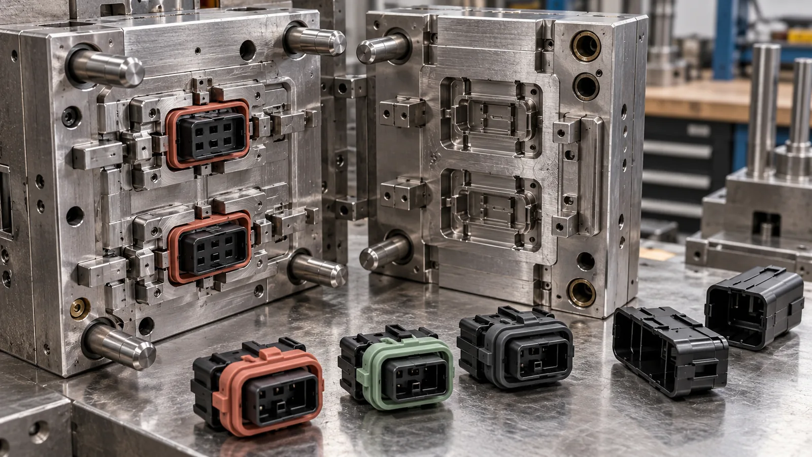
MOLD & TOOLING OVERVIEW
A custom silicone connector seal overmold tool must locate every rigid insert consistently while forming a controlled sealing collar without damaging terminals, latches or mating features. Naike Silicone reviews the buyer's connector CAD, insert tolerance, critical shutoff surfaces, sealing interface, material combination and assembly route before defining the tool and fixture concept.
The DFM stage considers insert loading orientation, poka-yoke features, nest support, cavity balance, silicone flow, venting, shutoff pressure, flash boundaries, undercuts and finished-part removal. Insert variation can change the overmold outcome, so the approved input should include measured connector samples and a documented acceptance range rather than only a nominal drawing.
First articles are checked for insert alignment, coverage, flash, voids, surface condition and agreed dimensions before any functional claim is released. Pull, leak, sectioning, media, temperature or cycle validation requires a named fixture, conditioning, sample count and acceptance criteria. Tooling cost, cavities, MOQ, materials and delivery timing are confirmed only after the design, evidence scope and production plan are approved.
Product page updated:
Request a B2B QuotationENGINEERING & APPROVAL EVIDENCE
Each stage addresses a different purchasing risk: manufacturability, functional fit and private-label presentation.
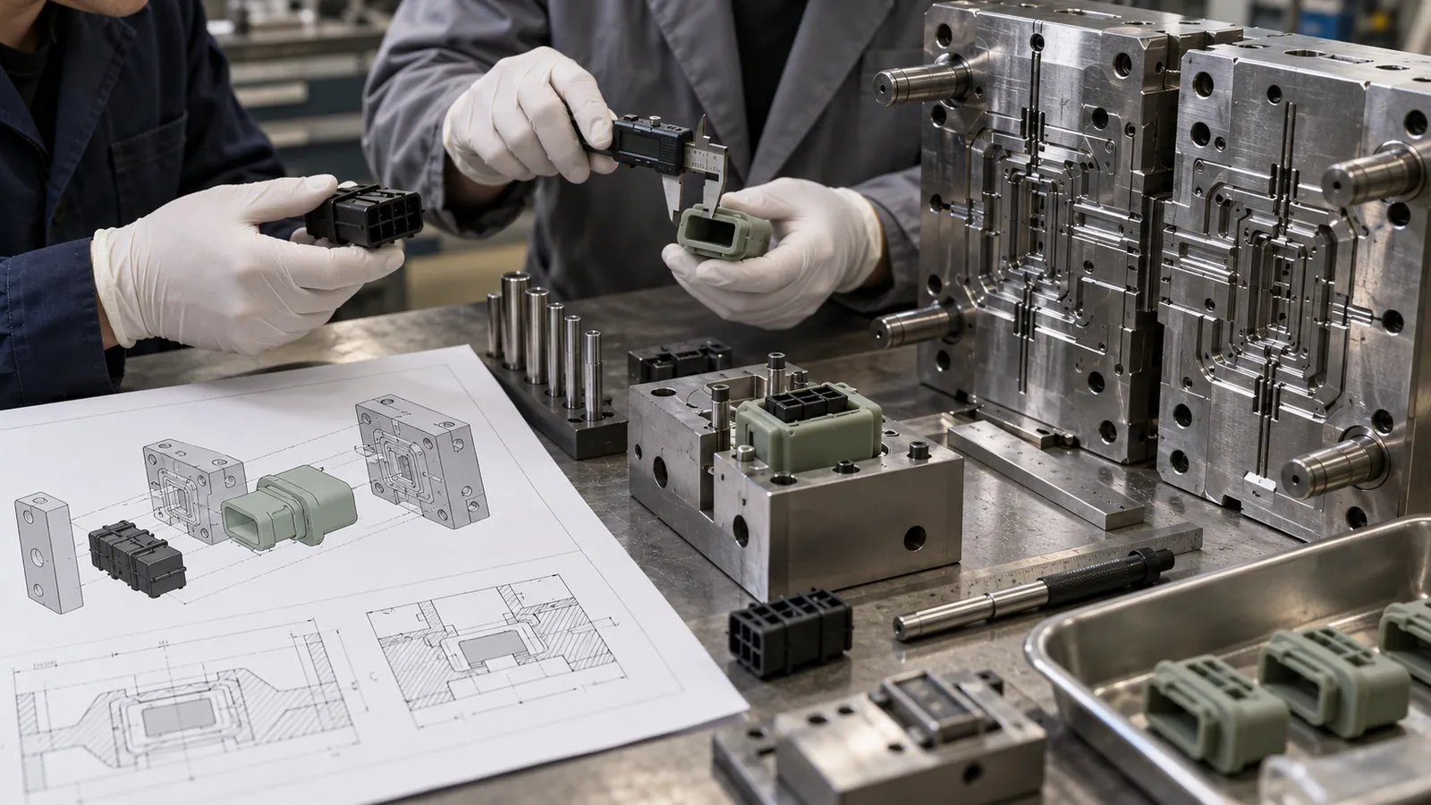
Illustrative scene: insert tolerance, loading direction, nest support, shutoffs, vents and removal are reviewed before tool release.
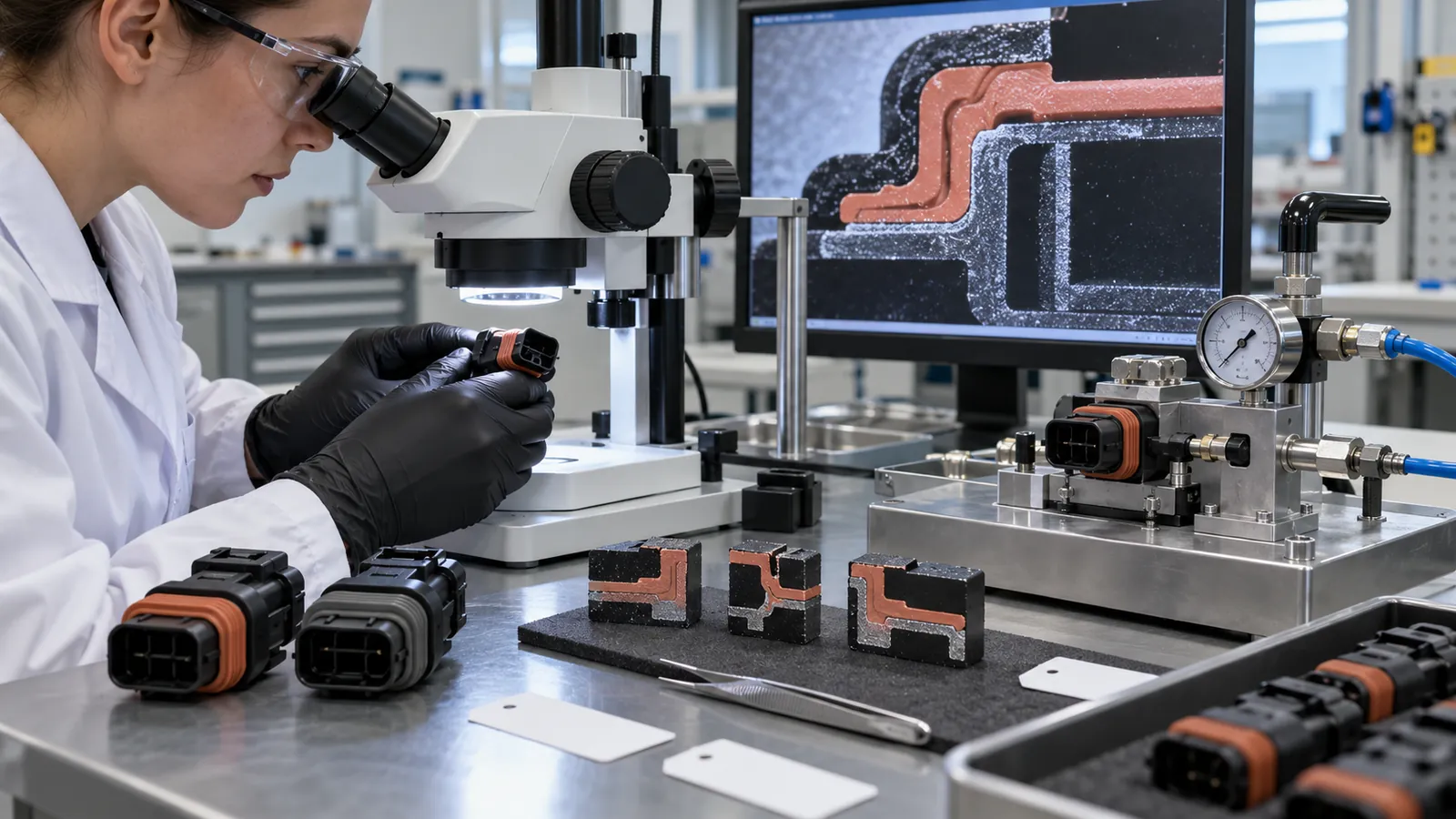
Illustrative scene: alignment, coverage, flash and section quality follow an approved inspection plan; the image does not imply a test result.
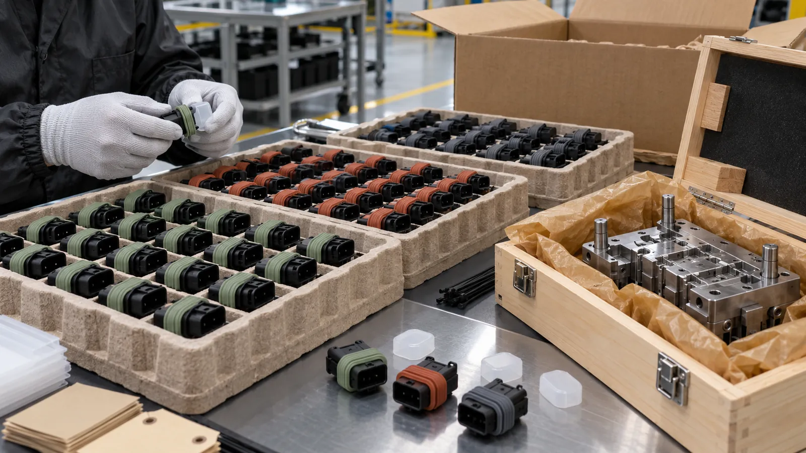
Illustrative scene: cavity identity, color, counts, protective caps, trays and tool preservation are approved before dispatch.
B2B SOURCING SNAPSHOT
Final terms depend on the approved specification, packaging, quantity and delivery plan.
| Control Point | Buyer Decision | Approval Basis |
|---|---|---|
| Insert definition | Connector CAD, measured tolerance, terminals, latches, datums and no-contact zones | Revision-controlled model plus representative physical inserts |
| Tool and nest | Loading orientation, support, poka-yoke, cavities, feed route, vents and release | DFM approval and traceable first-article cavity identity |
| Seal geometry | Collar profile, lips, local wall, compression interface and flash boundary | Controlled drawing and mating-fixture review |
| Material interface | Insert resin, silicone compound, cure, hardness, primer or surface preparation if applicable | Compatibility review and project-specific evidence |
| Validation scope | Dimensions, coverage, sectioning, pull, leak, media, temperature or cycles | Buyer-approved method, conditioning, samples and acceptance criteria |
| Production release | Tool revision, cavity controls, golden sample, inspection plan and change record | Formal approval before repeat production and shipment |
Each project is reviewed as a complete product specification.
Develop fixed or replaceable nests around the connector datums, tolerance range and safe loading direction.
Tune collar, lip, flange and local wall geometry around the named mating interface and compression target.
Protect functional plastic features while controlling silicone flow, trapped air and accessible flash boundaries.
Review insert resin, silicone compound, hardness, cure and any approved surface preparation as one system.
Add cavity identity and an inspection route that separates insert, tooling and process variation.
Specify terminal caps, trays, color segregation, counts, labels and carton protection for the actual assembly line.
B2B BUYER FAQ
These answers define the decisions required before tooling, sampling and a reliable quotation.
Send connector CAD and drawings, physical inserts, tolerance data, sealing geometry, material requirements, target quantity, validation plan, destination and pack-out needs. Identify terminals, latches and mating surfaces that the tool must not contact.
The nest references stable datums and supports the insert against molding loads. Loading orientation, poka-yoke, retention and removal are reviewed with measured samples so nominal CAD does not hide incoming variation.
DFM defines shutoff surfaces, local pressure support, vents and permitted trimming zones. First articles are inspected at critical plastic-to-silicone boundaries before the tool revision is approved.
Replaceable nests or shared tooling may be considered when interfaces and envelope dimensions are compatible. Each variant still needs its own controlled input, sample approval, cavity identification and validation scope.
No. Adhesion depends on resin, surface condition, silicone chemistry, cure, geometry and any approved preparation. Mechanical retention and chemical bonding should be distinguished and validated for the selected combination.
The buyer and factory define fixtures, assembly, conditioning, media, load direction, rate, repetitions and acceptance limits. Results apply only to the tested insert, silicone, geometry and method.
Yes. Color, cavity identity, count, tray, protective cap and carton can be coordinated for downstream assembly, subject to an approved pack-out sample and traceability plan.
Connector complexity, insert handling, cavities, shutoff precision, material combination, validation, automation and packaging affect the plan. Final commercial terms follow approved DFM and current capacity review.
CATEGORY-SPECIFIC REVIEW
Sketches, samples, drawings, CAD files and measurable performance requirements.
Parting lines, draft, wall thickness, venting, cavities and demolding strategy.
Dimensions, function, color, finish, logo and golden-sample signoff.
Controlled specifications, mold maintenance, batch inspection and change records.
INQUIRY CHECKLIST
Providing clear requirements helps us evaluate tooling, samples, price and lead time.
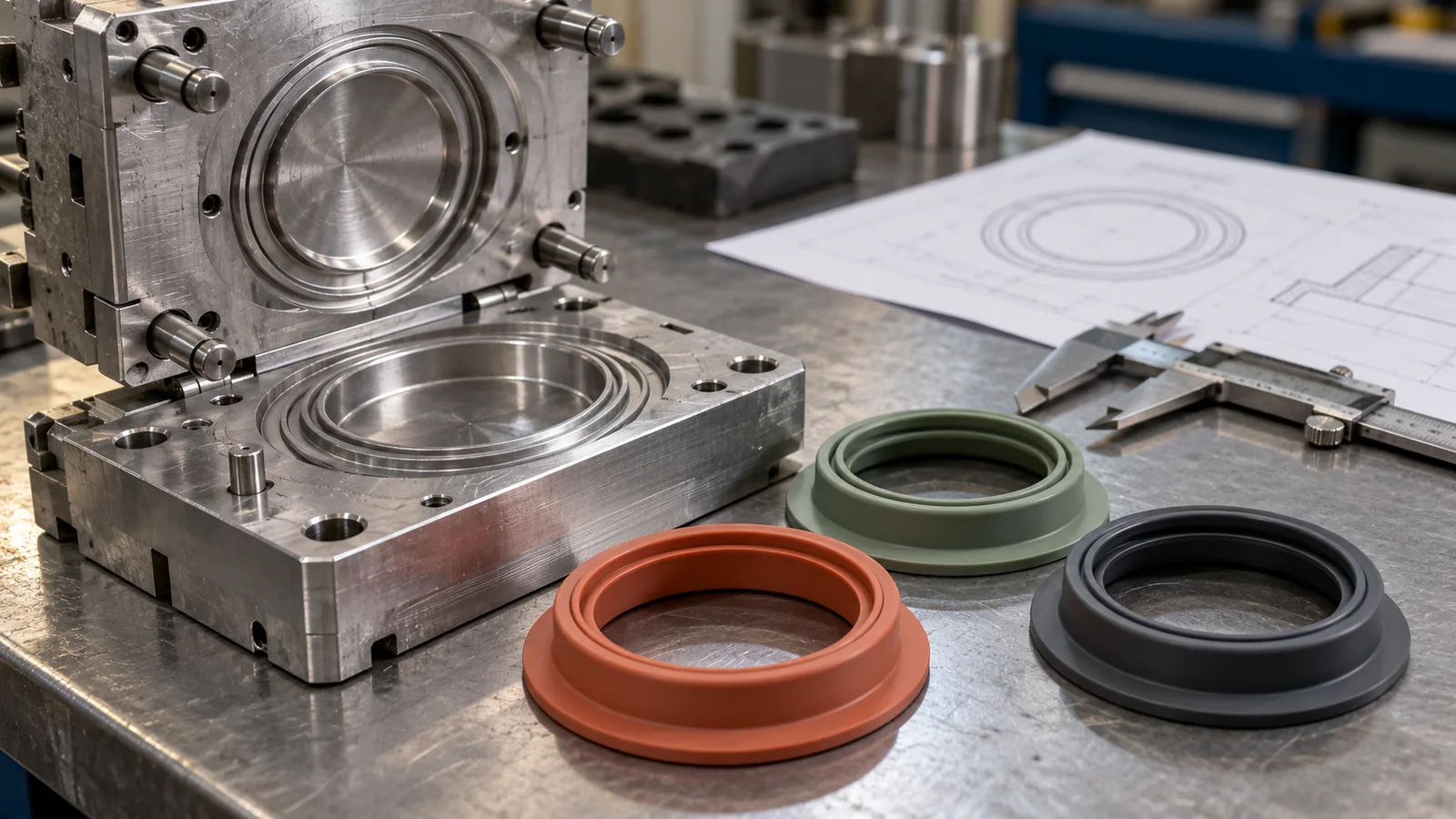
Prototype silicone gasket tooling developed around sealing geometry, parting-line control, first-article measurement and a documented path to production tooling.
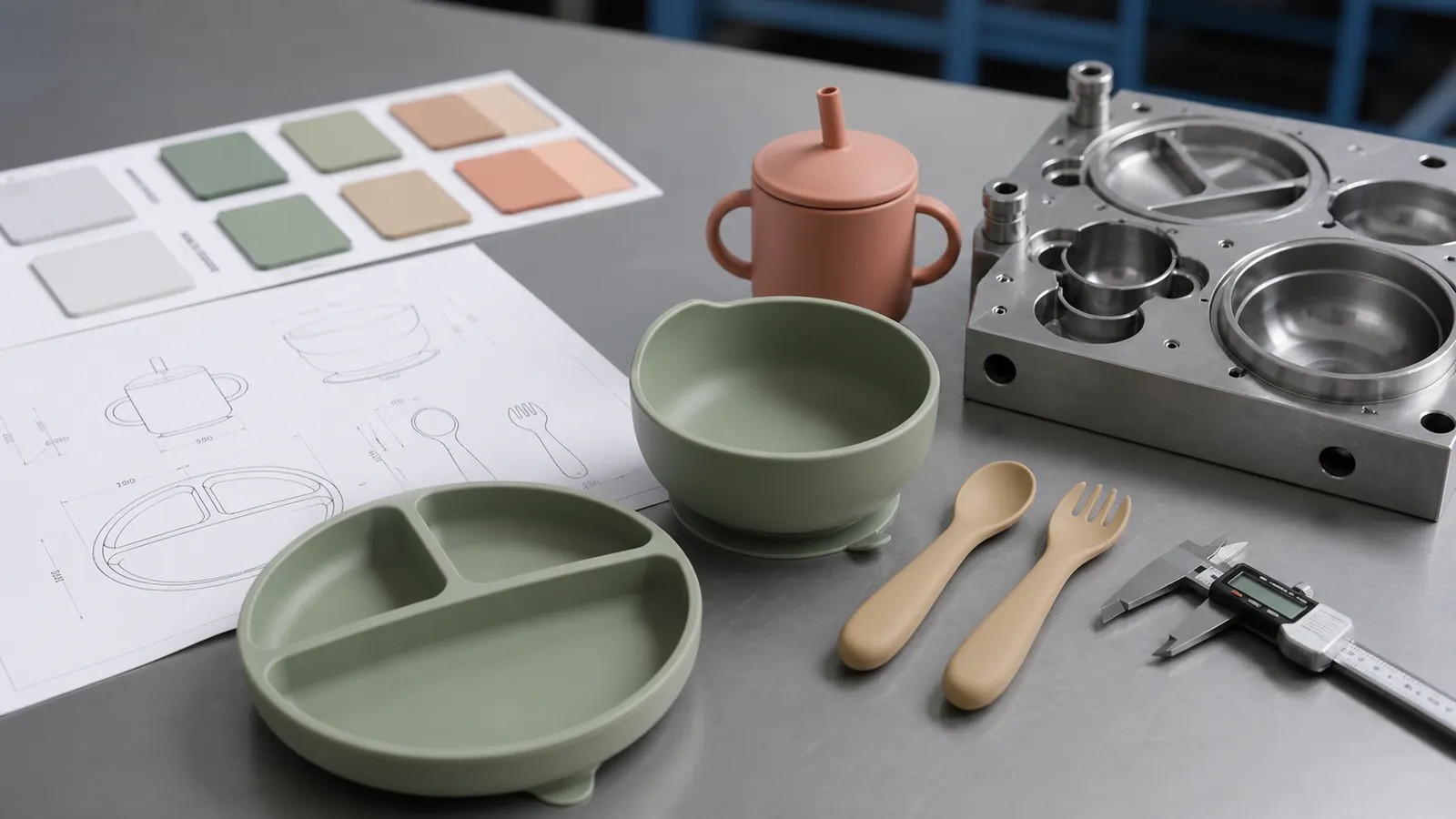
Compression tooling developed around plate flatness, suction geometry and clean demolding.
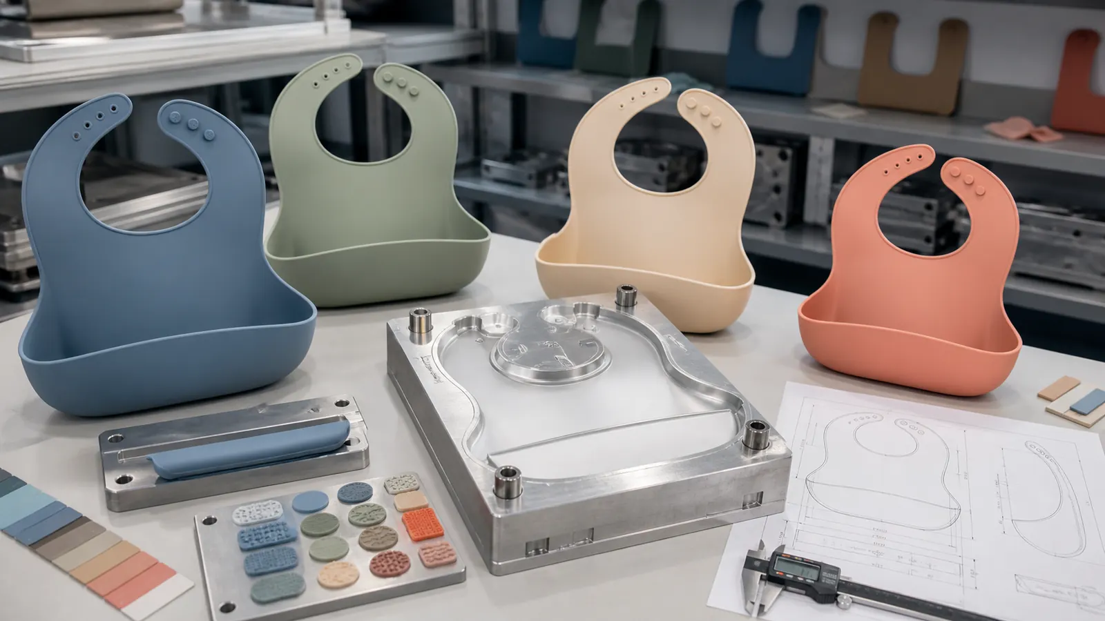
Dedicated bib tooling for thin flexible panels, adjustable neck details and a stable catch pocket.
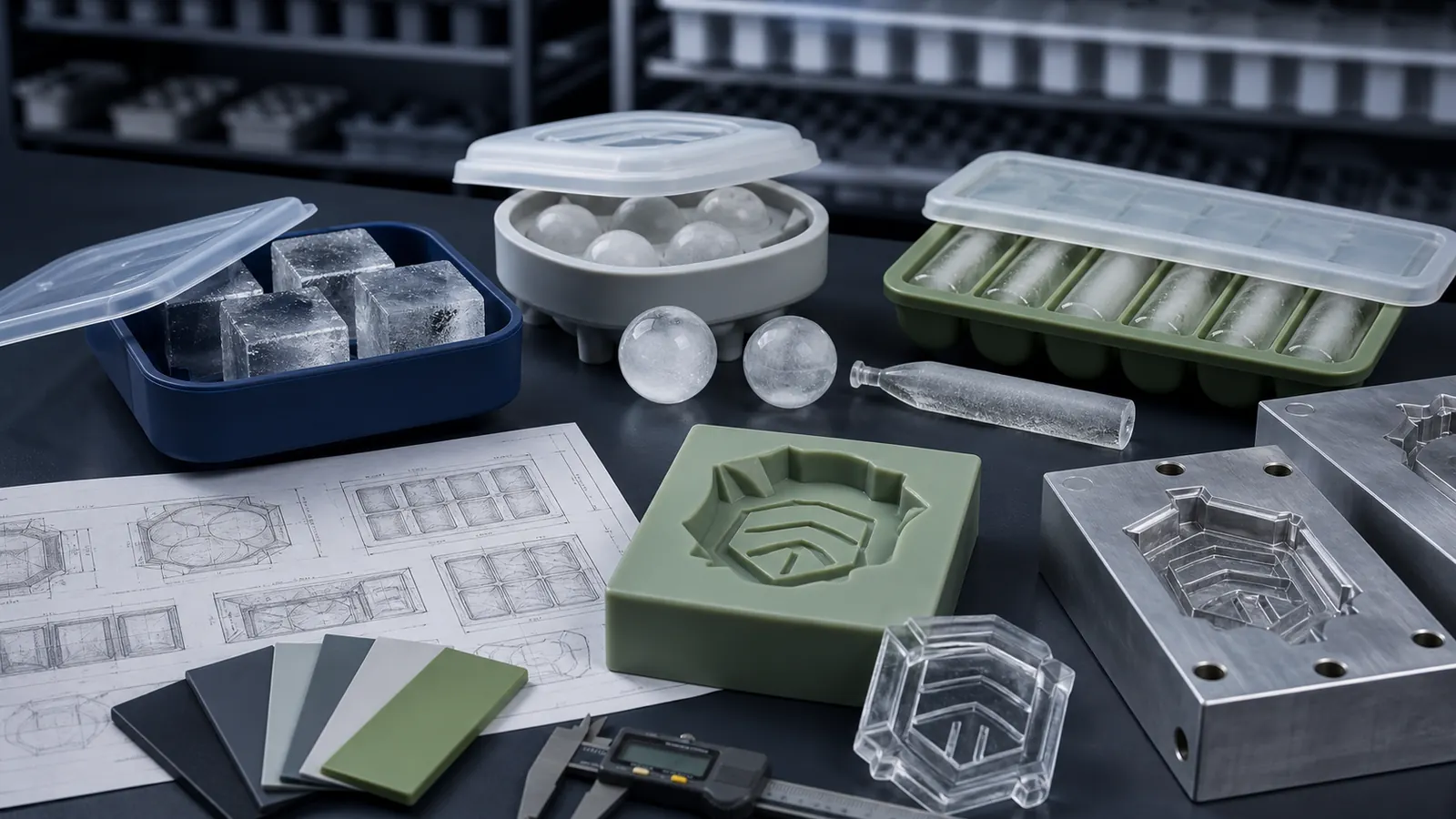
Custom-cavity tooling for branded ice shapes, freezer release and consistent fill volume.
B2B PROJECT INQUIRY
Share the intended product, destination market, order quantity and launch plan. Our project team will review the information and identify the next practical step.
Drawings are helpful but not required. A sketch, reference photo or physical sample can be used for an initial discussion.
GENERAL SOURCING INQUIRY